Monday 28 March 2016

Call setup procedure. Quick Reference


Following is the over protocol sequence being exchanged between UE and Network. Actually understanding all the details of these steps would be the goal of your whole LTE career.

2) MIB
3) SIB 1
O3) ESM : ESM Information Request
O4) ESM : ESM Information Response
O5) EMM : EMM Identity Request
O6) EMM : EMM Identity Response
O7) EMM : EMM Information
19) RRC : RRC Connection Release
22) < MO or MT call > : In MT call, Paging should be sent.
32) RRC : RRC Connection Release

Source: sharetechnote

Wednesday 23 March 2016

QCI in LTE


QCI stands for QoS Class Identifier. This is a special indentifier defining the quality of packet communication provided by LTE. The QoS concept as used in LTE networks is class-based, where each bearer type is assigned one QoS Class Identifier (QCI) by the network. The QCI is a scalar that is used within the access network (namely the eNodeB) as a reference to node specific parameters that control packet forwarding treatment, for example scheduling weight, admission thresholds and link-layer protocol configuration.
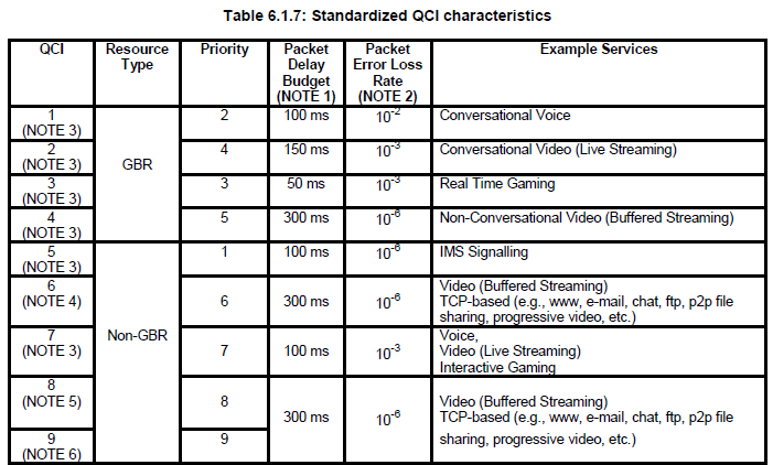
The QCI is also mapped to transport network layer Layer parameters in the relevant Evolved Packet Core (EPC) core network nodes (for example, the PDN Gateway (P-GW),Mobility Management Entity (MME) and Policy and Charging Rules Function (PCRF) ), by preconfigured QCI to Differentiated Services Code Point (DSCP) mapping. According to 3GPP TS 23.203, 13 QCI values are standardized and associated with QCI characteristics, in term of packet forwarding treatment that the bearer traffic receives edge-to-edge between the UE and the P-GW. Scheduling priority, packet delay budget and packet error loss rate are the set of characteristics defined by the 3GPP standard and they should be understood as guidelines for the pre-configuration of node specific parameters to ensure that applications/services mapped to a given QCI receive the same level of QoS in multi-vendor environments as well as in roaming scenarios. The QCI characteristics are not signalled on any interface.

(Table from TS 23.203)
Note : GBR stands for Guaranteed Bit Rate

The specific QCI value is allocated for each UE and is informed to UE via 'Activate EPS bearer context request' message.

There are two types of EPS bearers: default and dedicated. In the LTE network, the EPS bearer QoS is controlled using the following LTE QoS parameters:
  ▶ Resource Type: GBR or Non-GBR
  ▶ QoS Parameters

  • QCI
  • ARP
  • GBR
  • MBR
  • APN-AMBR
  • UE-AMBR
Every EPS bearer must have QI and ARP defined. The QCI is particularly important because it serves as reference in determining QoS level for each EPS bearer. In case of bandwidth (bit rate), GBR and MBR are defined only in GBR type EPS bearers, whereas AMBR (APN-AMBR and UE-AMBR) is defined only in Non-GBR type EPS bearers. 
Below, we will explain the LTE QoS parameters one by one.


Resource Type = GBR (Guaranteed Bit Rate)


For an EPS bearer, having a GBR resource type means the bandwidth of the bearer is guaranteed. Obviously, a GBR type EPS bearer has a "guaranteed bit rate" associated (GBR will be further explained below) as one of its QoS parameters. Only a dedicated EPS bearer can be a GBR type bearer and no default EPS bearer can be GBR type. The QCI of a GBR type EPS bearer can range from 1 to 4.


Resource Type = Non-GBR


For an EPS bearer, having a non-GBR resource type means that the bearer is a best effort type bearer and its bandwidth is not guaranteed. A default EPS bearer is always a Non-GBR bearer, whereas a dedicated EPS bearer can be either GBR or non-GBR. The QCI of a non-GBR type EPS bearer can range from 5 to 9.


QCI (QoS Class Identifier)


QCI, in an integer from 1 to 9, indicates nine different QoS performance characteristics of each IP packet. QCI values are standardized to reference specific QoS characteristics, and each QCI contains standardized performance characteristics (values), such as resource type (GBR or non-GBR), priority (1~9), Packet Delay Budget (allowed packet delay shown in values ranging from 50 ms to 300 ms), Packet Error Loss Rate (allowed packet loss shown in values from 10-2 to 10-6. For more specific values, search on Google for "3GPP TS 23.203" and see Table 6.1.7 in the document. For example, QCI 1 and 9 are defined as follows:
QCI = 1
: Resource Type = GBR, Priority = 2, Packet Delay Budget = 100ms, Packet Error Loss Rate = 10-2 , Example Service = Voice
QCI = 9
: Resource Type = Non-GBR, Priority = 9, Packet Delay Budget = 300ms, Packet Error Loss Rate = 10-6, Example Service = Internet
QoS to be guaranteed for an EPS bearer or SDF varies depending on the QCI values specified.
QCI, though a single integer, represents node-specific parameters that give the details of how an LTE node handles packet forwarding (e.g. scheduling weights, admission thresholds, queue thresholds, link layer protocol configuration, etc). Network operators have their LTE nodes pre-configured to handle packet forwarding according to the QCI value.
By pre-defining the performance characteristics of each QCI value and having them standardized, the network operators can ensure the same minimum level QoS required by the LTE standards is provided to different services/applications used in an LTE network consisting of various nodes from multi-vendors.    
QCI values seem to be mostly used by eNBs in controlling the priority of packets delivered over radio links. That's because practically it is not easy for S-GW or P-GW, in a wired link, to process packets and also forward them based on the QCI characteristics all at the same time (As you may know, a Cisco or Juniper router would not care about delay or error loss rate when it processes QoS of packets. It would merely decide which packet to send first through scheduling (WFQ, DWRR, SPQ, etc.) based on the priority of the packets (802.1p/DSCP/MPLS EXP)). 


ARP (Allocation and Retention Priority)


When a new EPS bearer is needed in an LTE network with insufficient resources, an LTE entity (e.g. P-GW, S-GW or eNB) decides, based on ARP (an integer ranging from 1 to 15, with 1 being the highest level of priority), whether to:

  • remove the existing EPS bearer and create a new one (e.g. removing an EPS bearer with low priority ARP to create one with high priority ARP); or
  • refuse to create a new one. 
So, the ARP is considered only when deciding whether to create a new EPS bearer or not. Once a new bearer is created and packets are delivered through it, the ARP does not affect the priority of the delivered packet, and thus the network node/entity forwards the packets regardless of their ARP values.
One of the most representative examples of using the ARP is an emergency VoIP call. So, an existing EPS bearer can be removed if a new one is required for a emergency 119 (911 in US, 112 in EC, etc) VoIP call. 


GBR (UL/DL)


This parameter is used for a GBR type bearer, and indicates the bandwidth (bit rate) to be guaranteed by the LTE network. It is not applied to a non-GBR bearer with no guaranteed bandwidth (UL is for uplink traffic and DL is for downlink traffic).


MBR (UL/DL)


MBR is used for a GBR type bearer, and indicates the maximum bit rate allowed in the LTE network. Any packets arriving at the bearer after the specified MBR is exceeded will be discarded.


APN-AMBR (UL/DL)


As you read the foregoing paragraph, you may wonder why a non-GBR type bearer does not have a "bandwidth limit"? In case of non-GBR bearers, it is the total bandwidth of all the non-GBR EPS bearers in a PDN that is limited, not the individual bandwidth of each bearer. And this restriction is controlled by APN-AMBR (UL/DL). As seen in the figure above, there are two non-GBR EPS bearers, and their maximum bandwidths are specified by the APN-AMBR (UL/DL). This parameter is applied at UE (for UL traffic only) and P-GW (for both DL and UL traffic).


UE-AMBR (UL/DL)


In the figure above, APN-AMBR and UE-AMBR look the same. But, please take a look at the one below.
A UE can be connected to more than one PDN (e.g. PDN 1 for Internet, PDN 2 for VoIP using IMS, etc.) and it has one unique IP address for each of its all PDN connections. Here, UE-AMBR (UL/DL) indicates the maximum bandwidth allowed for all the non-GBR EPS bearers associated to the UE no matter how many PDN connections the UE has. Other PDNs are connected through other P-GWs, this parameter is applied by eNBs only.


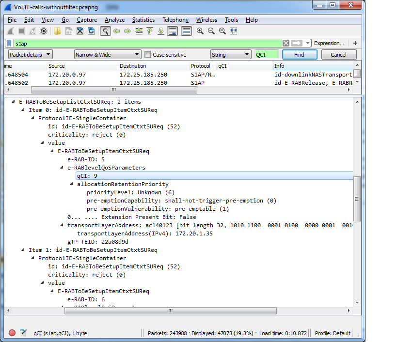
Sample wireshark log of configuring QCI 9:

Friday 18 March 2016

All about PDCCH, CCE, Aggregation Level


PDCCH ( Physical downlink Control Channel ) :- This channel carries the control information about the data being transmitted on the current subframe and the information about the resources which UE need to use for the uplink data. That means it is mandatory for the UE to decode it successfully if it wants to send some data or receive something.


After knowing PDCCH, I personally feel that it is the heart of LTE . So we should try to understand it completely that:-

What information it carries?
Where it carries the information?
And for whom it carries the information?

PDCCH carries a message called DCI ( Downlink Control Information ) which includes resource assignments for a UE or group of UE's. EnodeB can transmit many DCI's or PDCCH's in a subframe. Actually enodeB need to send a lot of parameters to the UE for its operation but there may be the cases that some information is not required for a particular UE.

For Example:- Some UE does not support MIMO ( Multiple Input Multiple Output ), so for that UE there is no need to send the MIMO related parameters because they will increase the signalling overhead.

There comes in the picture the different formats for sending the information which are called DCI formats. Even we would not like to have so many formats because they will increase the complexity. So to cover the most useful cases we have following DCI formats:-

DCI format 0 is used for uplink allocation, all other formats are used for allocating the resources in downlink. 
  • Format 0 for transmission of resources to UE for sending their uplink data
  • Format 1 for downlink allocation of resources for Single Input Multiple Output (SIMO)case
  • Format 1A for downlink allocation of resources for SIMO operation or allocating a dedicated preample signature to a UE for random access
  • Format 1B for transmission control information of Multiple Input Multiple Output (MIMO) rank 1 based compact resource assignment
  • Format 1C for very compact transmission of PDSCH assignment
  • Format 1D same as format1B with additional information of power offset
  • Format 2 and Format2A for transmission of DL-SCH allocation for closed and open loop MIMO operation, respectively
  • Format 3 and format3A for transmission of TPC command for an uplink channel       
We will explain the structure of each format later with their sizes and thorough explanation of their specific use.

Allocation of resources happens in terms of CCE ( Control Channel Elements ).

1 CCE = 9 continuous REG's ( Resource element Group )
1 REG = 4 RE ( Resource Element )

CCE allocation for PDCCH :- 
 PDCCH uses the resources present in first n OFDM symbols where
n - Value present in PCFICH ( Number of OFDM symbols )

So the number of CCE's present to transmit the control information will be variable depending on the
  • PCFICH value
  • Bandwidth of the system from 1.4 Mhz to 20 Mhz.
  • Number of antenna ports present which in turn will effect the reference signals present.

Lets take an example for the number of CCE available calculation:-
Step -1 :- We need to find the total number of RE's available in first n OFDM symbols where n is coming from the value of PCFICH.
Suppose   n = 3

Total RE's =  n * x * y

n - PCFICH value
x - number of subcarriers in 1 RB
y - total number of RB's considering 10 Mhz bandwidth

Total RE's = 3 * 12 * 50 = 1800 RE's

RE's for PDCCH = Total RE's -
                              Number of RE's used for reference signals -
                              Number of RE's used in PHICH -
                              Number of RE's used in PCFICH 
                                                                       
CCE's available for PDCCH = RE's for PDCCH /36

 as 1 CCE = 36 RE's.

eNodeB uses the PDCCH for sending the control information for a particular UE or a group of UE's. It means eNodeB uses the PDCCH  for some broadcast information also which is common for all the UE's. So to make that process easier eNodeB divided its CCE's into two parts which we call them as search space:
  1. Common search space :- It consists of CCE's which are used for sending the control information which is common for all the UE's .Maximum number of CCE present in common search space is 16. For Example:- Common search space CCE's are used by eNodeB for sending the control information of SIB's which is common for all UE's. 
  2. UE specific search space :- CCE's belonging to UE specific space are used for sending the control information for a particular UE only. That means information present on UE specific CCE's can only be decoded by a specific UE.
eNodeB can also send the control information for a specific UE on the common search space

Lets suppose there are total 100 CCE's eNodeB has for sending the control information combining both common space and UE specific search space.


Suppose enodeB has used 85th CCE number for a UE named ravan for sending his control information.

Now how the Ravan will come to know which CCE he needs to decode for getting his information. Either he needs to scan all 100 CCE's one by one and try to find the information. This procedure will consume a lot of battery power for the UE. So to simplify this process,

eNodeB has fixed some indexes for a particulat UE based on the rnti and the subframe, so now ravan needs to find his control information only on those specific CCE indexes.

How eNodeB calculate those CCE indexes for a UE:-

First we should be familiar with some terms used in this procedure:-
  • Aggregation Level :- It is defined as number of CCE's used for sending a control information. Its values can be 1,2,4 and 8. Suppose for UE named ravan eNodeB is using some DCI format whose size comes out to be 90 bits after applying the code rate.
    • Code rate:- It is mainly a physical layer funda for sending the information in a redundant way such that chances of UE successfully decoding it gets increased. 
          As we know that :-

          1 CCE = 36 RE's
          1 RE = 2 bits ( For QPSK modulation)
                      4 bits( For 16 QAM )
                      6 bits ( For 64 QAM)

          And eNodeB uses QPSK modulation technique for PDCCH ,
          Number of bits in 1 CCE = 36 * 2 = 72 bits.

          In the example for UE ravan eNodeb needs to send 90 bits , so it need to use atleast 2 CCE's for the control information on PDCCH. It means it will send the control information with aggregation level 2. 

         It is also possible that enodeB uses a higher aggregation level( more number of CCE's) even if the bits transmitted on PDCCH are less. This happens when channel conditions are bad , so to provide more redundant information to UE such that it can decode the PDCCH.
    •  PDCCH candidates :- Number of CCE indexes serached by a UE in a subframe for a particular search space. These values are fixed by spec 36213 as mentioned in table :-

    Search space 
    Number of PDCCH candidates 
    Type
    Aggregation level 
    Size [in CCEs]
    UE-specific
    1
    6
    6
    2
    12
    6
    4
    8
    2
    8
    16
    2
    Common
    4
    16
    4
    8
    16
    2

    •  PDCCH Format :- There are four PDCCH formats available as shown below


     The set of indexes searched by a UE depends on a formula given by spec as:-
    where Yk is defined as


    L - Aggregation level

    A PDCCH consisting of n consecutive CCE's may only start on a CCE index fulfilling
    i mod n = 0
    where i  =  CCE number

    For Example:-  
    eNodeB wants to allocate PDCCH for some UE or group of UE's on aggregation level 4 ( Means 4 CCE's are required), Then it can only allocate CCE's starting with indexes which satisfies

    (CCE index) mod 4 = 0


    How to find CCE indexes on common search space:-
    As shown in table eNodeB uses only aggregation level 4 and 8 for the allocation in common search space .

    Maximum number of CCE's present in common search space is fixed as 16. If the total number of CCE's available in the system are less than 16 for any bandwidth then all the CCE's will be present in common search space.

    The position of Common search space CCE's is always fixed starting from the first CCE index.


    For example:-


    We have 100 CCE's belonging to PDCCH as shown above from CCE index 0 to 99.

    As we know that starting CCE's are common search space CCE's , so in the diagram green color CCE's are common search space CCE's from index 0 to 15.

    Suppose eNodeB wants to allocate CCE's for SIB on common search space for aggregation level 4
    And we know that it should satisfy the formula
    1. (CCE Index ) mod 4 = 0,

    2. And from the table above , the number of PDCCH candidates ( starting CCE indexes) for aggregation level 4 in common space can be 4.

    By meeting the above two conditions 4 indexes will be supported by aggregation level 4 in common space as

    CCE index 0 - will contain consecutive CCE's from 0 to 3
    CCE index 4 - will contain consecutive CCE's from 4 to 7 
    CCE index 8 - will contain consecutive CCE's from 8 - 11 
    CCE index 12 - will contain consecutive CCE's from 12 -15


    Similarly if eNodeB wants to allocate with aggregation level 8, then possible indexes meeting the two conditions will be

    CCE index 0 - will contain consecutive CCE's from 0 to 7
    CCE index 8 - will contain consecutive CCE's from 8 to 15

    As we know that UE does the blind PDCCH decoding , means it does not have any idea about the aggregation level or DCI format used by the eNodeB. So a UE in common space needs to make

    (4 try in aggregation level 4 + 2 try in aggregation level 8 )  * DCI format supported for common space

    only small sizes DCI formats are supported in common search space as 0/1A/3/3A/ and 1C

    so if enodeB supports 1A and 1C DCI formats, so UE needs to do 12 tries maximum to decode its PDCCH information.


    How to find the CCE indexes in UE specific search space in a subframe:-

    According to the formulas in spec 36213 as:-
    The set of indexes searched by a UE  in a subframe is:-
    where Yk is defined as

    if k =0 , Y-1 = RNTI value for that UE ( As given in spec 36213 sec 9.1.1 )

    A = 39827
    D = 65537

    Lets take an example:-

    Subframe number = 0
    Aggregation level = 1

    We know from the table above that for aggregation level 1, number of PDCCH canditates ( CCE indexes) can be 6.

    Yk = (A * Yk-1 ) mod D
    k = subframe number
    As k = 0
    Yk-1 = RNTI value for that UE, lets suppose its 100.
    Yk = (39827 * 100) mod 65537 
          = 50480

    CCE index =  

    L = aggregation level
    i = 0 to (Aggregation Level - 1) 
    Ncce = Number of CCE's available for PDCCH ( suppose 100) 
    m' = 0 to ( Number of PDCCH canditates -1 )
    CCE index = 1 { (50480 + 0 ) mod (100/1)} + 0 
                      = 80

    So first CCE index for aggregation level 1 for this UE in subframe 0 will be 80.

    Lets calculate next CCE index for the same UE in the same subframe.

    Yk value changes with the subframe only so withion the subframe same value will be used

    CCE index = 1 { ( 50480 + 1 ) mod ( 100 /1 )} + 0
                      = 81

    Similarly you can calculate the remaining CCE indices for this UE in the current subframe

    Lets try to find the CCE indices for subframe 1 now with aggregation level 2:-

    As we know that Yk value changes with subframe

    Yk = (A * Yk-1) mod D
         = (39827 * 50480) mod 65537
         = 53948
    Yk-1 will be the value calculated for subframe 0 
    For aggregation level two also
    m' will be 0 to 5 as number of PDCCH candidates are 6 for aggregation level 2
    CCE index = 2 {(53948 + 0) mod (100/2)} + 0
                     =96
    As in Aggregation level 2, two CCE's will be allocated for the same PDCCh candidate

    Second CCE will be = 2{(53948 +0)mod (100/2)} + 1 
                                    = 97
    So first CCE index for this UE in subframe 1 for aggregation level 2 will be 96. This PDCCH candidate will contain 2 CCE's with indexes 96 and 97.

    In similar ways UE can find the CCE indexes available in all subframes for the different aggregation levels.


    CCE Allocation Examples:-


    • If terminal A is using the CCE's 16 to 23 then terminal B cannot be addressed on Aggregation level 4 as the CCE's are already blocked by terminal A.
    • We can also notice that, CCE's 24- 31 belongs to both of the UE's PDCCH candidate set for aggregation level 8. That means overlap can also happen but eNodeB can actually use it for one terminal either A or B.
    • For point 1 like case, common search space CCE's can be used to resolve the contention. This is also another inportant use of common search space.
    • It is also clear that first 16 CCE's are used for common search space in both aggregation level 4 and 8.


     How EnodeB decides which DCI Format to use:-
    It is decided by enodeB on the basis of transmission mode and the RNTI type used for that particular PDCCH.

    RNTI types:-
    • SI- RNTI :- Used for transmission of system information messages.
    • RA-RNTI :- Used for PRACH responses.
    • P-RNTI :- Used for the paging messages
    • C-RNTI :- Used for the transmission to a specific UE after RACH.
    • T-CRNTI :- Mainly used during Rach.
     There are tables present in spec 36213 in sec 7.1 which describes which format to use.

     I am consolidating that information from spec in a easy way to understand. 
    Usually all the common information gets scheduled in common search space with the CRC scrambled with all RNTI's except CRNTI. We use DCI format 1A or 1C irrespective of Transmission mode.

    Please find the table for the mapping :- 

    • PDCCH order is also transmitted with DCI format 1A.  
    How EnodeB decides the Aggregation Level to use :-
    It is decided on the basis of size of DCI and the CQI ( channel quality indicator ) value received in uplink. The size of different DCI formats is defined in spec. After selecting the DCI format we know the number of bits needs to send on PDCCH after applying the code rate.
    As we know that in 1 CCE 72 bits can be transmitted as QPSK modulation is used in PDCCH. After considering the DCI size and the CQI value, eNodeB decides the aggregation level to use or the number of CCE's required for the control information for this particulat DCI. 


    Blind Decoding of PDCCH by UE :- 
    UE does the blind decoding because:-
    • UE does not have idea about the CCE's used by PDCCH
    • UE does not know the aggregation level used by eNodeB
    • UE do not have idea about the DCI format used by eNodeB 
     Steps followed by UE for the blind decoding of PDCCH:-

    After each blind detection UE checks the CRC with the corresponding RNTI. If CRC is decoded successfully with that RNTI, UE can find the DCI format from the payload size and the RNTI in that PDCCH . 

    Important points about PDCCH :- 
    •  ULSCH PDCCH or DCI format 0 which is used for uplink grant is scrambled with Antenna selection mask  . It is done to intimidate the UE about the antenna port it needs to use for its transmission.
    • PDCCH shall be transmitted on the same set of antenna ports as PBCH.
    • PDCCH is transmitted in starting OFDM symbols to save battery at UE.
    • In one subframe or 1 ms , multiple DCI's needs to be send by eNodeB for sending the data to different UE's.
    • For 1 UE, eNodeB can send multiple DCI's if it needs to send data and  give uplink grant in the same tick.
    • UE needs to keep on decoding CCE's if it is expecting more than one DCI's.

    Source : http://nitintayal-lte-tutorials.blogspot.in/2013/05/all-about-pdcch-and-cce-allocation.html?showComment=1458227800189